A Modbus RTU slave that never answers is often not a broken UART, a wrong baud rate, or a mysterious silicon bug. The frame looks fine in a logic analyzer. Function code and register address match the spec. Then you notice the last two bytes: the CRC does not match what the device computed. That mismatch is the most common integrity failure in industrial serial work, and it is almost never because polynomial division itself is hard. If you need to reproduce a CRC-16/MODBUS result while you read, the CRC Calculator can compute the same catalogue-defined variant locally in the browser.
This post is not a CRC primer. The polynomial picture and the Ethernet / CAN / 1-Wire landscape are already in Data Integrity Verification with CRC. The question here is narrower and more annoying: why do two implementations that both say "CRC-16" disagree on a Modbus frame, and how do you isolate the cause in a few minutes?
Start With the Check Value, Not the Live Frame
Greg Cook's Catalogue of parametrised CRC algorithms treats every named CRC as a parameter set, not a marketing label. The parameters that actually change the output are width, generator polynomial (poly), initial register value (init), input reflection (refin), output reflection (refout), and final XOR (xorout). The catalogue also publishes a check value: the CRC of the nine ASCII bytes 123456789. That single vector is the cheapest way to tell whether your code, library, or online tool is running the algorithm you think it is.
For CRC-16/MODBUS the parameters are:
If you feed 123456789 as ASCII (not as hex 31 32 33... typed by hand unless you really mean those bytes) and you do not get 0x4B37, stop. Do not debug the PLC, the transceiver, or the rest of the PDU yet. The calculator or the firmware routine is a different algorithm, no matter what the dropdown is labelled.
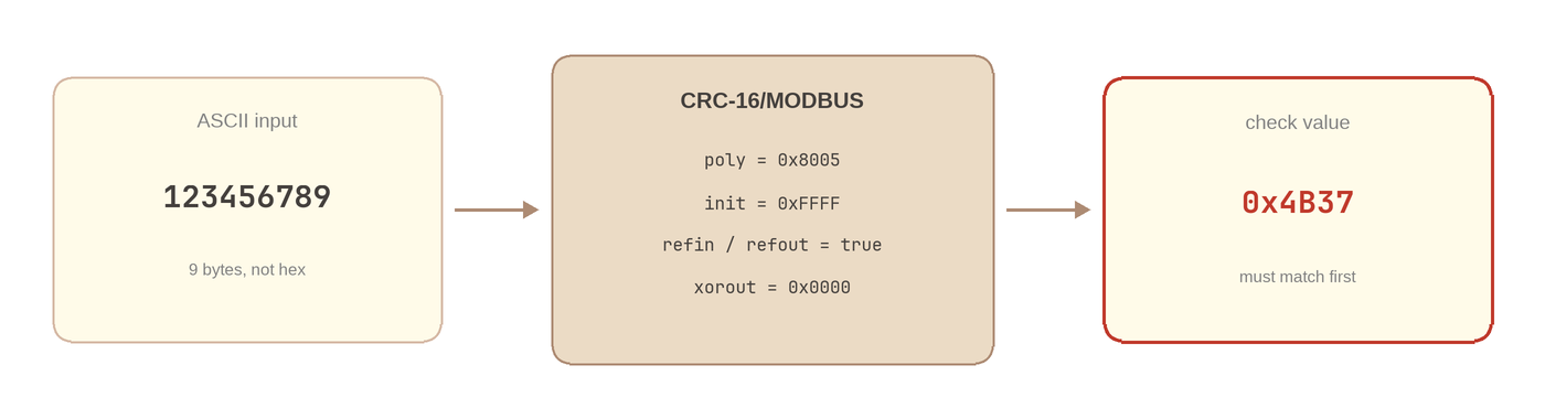
The catalogue check value is the CRC of ASCII "123456789". For CRC-16/MODBUS that result must be 0x4B37 before you trust the tool on a real frame.
Why does this catch so many bugs? Because the next-door neighbours of CRC-16/MODBUS look similar on paper. CRC-16/ARC uses the same polynomial and the same reflection, but init=0x0000. Its check value is 0xBB3D. CRC-16/IBM-3740 (often sold in UIs as "CCITT-FALSE") uses poly=0x1021, init=0xFFFF, and no reflection; its check value is 0x29B1. Pick either of those by accident and every Modbus frame you compute will be consistently wrong — which is worse than a random error, because the wrong CRC looks systematic and "implementation-like."
Same Name, Different Algorithm
Embedded datasheets, Stack Overflow answers, and vendor libraries all say "CRC-16." That string is not an algorithm. Ross Williams's A Painless Guide to CRC Error Detection Algorithms is still the document that makes the parameter list explicit; without it, two engineers can both be "correct" and still not interoperate.
A compact comparison for the three mix-ups that show up in Modbus debugging:
| Catalogue name | poly | init | refin / refout | check |
|---|---|---|---|---|
| CRC-16/MODBUS | 0x8005 | 0xFFFF | true / true | 0x4B37 |
| CRC-16/ARC | 0x8005 | 0x0000 | true / true | 0xBB3D |
| CRC-16/IBM-3740 | 0x1021 | 0xFFFF | false / false | 0x29B1 |
The Modbus Application Protocol spec (V1.1b3, PDF) describes the RTU frame and points implementers at CRC-16 with the reflected 0xA001 polynomial — that is CRC-16/MODBUS, not ARC and not CCITT-FALSE. The low-level bit loop you see in firmware is usually:
0xA001 is not a different polynomial from 0x8005. It is the bit-reversed form used when refin/refout are true and you shift right. If your code XORs 0x8005 while shifting left, you have silently switched families. The check value will not be 0x4B37.
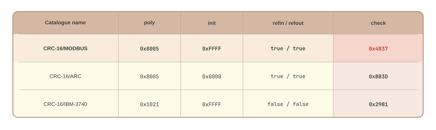
Three 16-bit CRCs that get confused in Modbus work. Only CRC-16/MODBUS has check=0x4B37.
When you already know you need CRC rather than a checksum or SHA-256, Checksum vs CRC vs Hash covers the security boundary. For this article the trap is smaller: CRC was the right family, the wrong member.
Byte Order on the Wire Is a Second Algorithm
Even after the 16-bit remainder is correct, Modbus RTU still has a packing rule. The CRC is appended low byte first (little-endian). A register value of 0xCDC5 becomes the two trailing bytes C5 CD on the UART.
Take a Read Holding Registers request, slave 0x01, starting at address 0, quantity 10:
If your calculator shows CDC5 and you append CD C5 because that is how you would write a 16-bit hex constant in a comment, the slave computes a different remainder over a different byte string and stays silent. That is the same class of bug as sending 0x2B A1 when the device expected A1 2B — the story in Understanding Endianness. Network byte order is big-endian; Modbus CRC bytes are not.

MODBUS RTU request layout. The CRC occupies the last two bytes, low byte first.
A practical check: if swapping the two CRC bytes makes the device answer, your polynomial path was already correct. You were fighting endianness, not CRC-16/ARC.
The Endian Converter is useful when the same dump mixes 16-bit register values (Modbus register payload is big-endian) with a little-endian CRC trailer. Those two conventions live in one frame. Mixing them in your head is a reliable way to waste an afternoon.
Hash the PDU, Not the Whole Capture
The CRC covers slave address + PDU, and nothing after. Typical mistakes:
- Including the two CRC bytes in the input, then wondering why the remainder is not zero. (For this reflected CRC, a correctly appended frame does reduce to a known residue — but if you are comparing against
0x4B37-style tools, you compute over the payload without the trailer.) - Including UART framing, timestamps, or a hex-dump address column copied from a terminal.
- Dropping the slave address and hashing only the function code and data.
- Feeding a hex string as ASCII: typing
01 03as the characters0,1, space,0,3instead of the bytes0x01 0x03.
The last one is especially common with web calculators. Input mode matters. ASCII "123456789" is the check vector. A Modbus frame is hex bytes. If the tool's HEX mode still interprets spaces as ASCII 0x20, your remainder will include those spaces as extra data.
Firmware that builds the frame in a buffer should CRC buf[0 .. pdu_len) and then write:
If you memcpy the uint16_t on a little-endian MCU, you often get the right order by accident. The same memcpy on a big-endian core, or a Python struct.pack('>H', crc), reverses it. Explicit byte stores are less clever and less wrong.
A Debugging Sequence That Usually Ends the Argument
When a capture and a calculator disagree, walk this list in order. Skipping to "rewrite the bit loop" is how the same bug survives a refactor.
- Prove the algorithm. ASCII
123456789→0x4B37. If not, change the named variant or theinit/refinflags until it matches. Do not touch the field frame yet. - Prove the input encoding. Paste the PDU as hex bytes with no CRC trailer. Confirm the tool is in HEX mode, not ASCII.
- Compare the 16-bit remainder, not the two on-wire bytes. If the remainder matches
0xCDC5for01 03 00 00 00 0Aand the device still NAKs, look at byte order next. - Swap the two CRC bytes in the transmitted frame once. If the slave answers, fix packing; leave the polynomial alone.
- Check coverage. Address byte included? CRC bytes excluded? No extra
0x00padding from a fixed-length buffer?
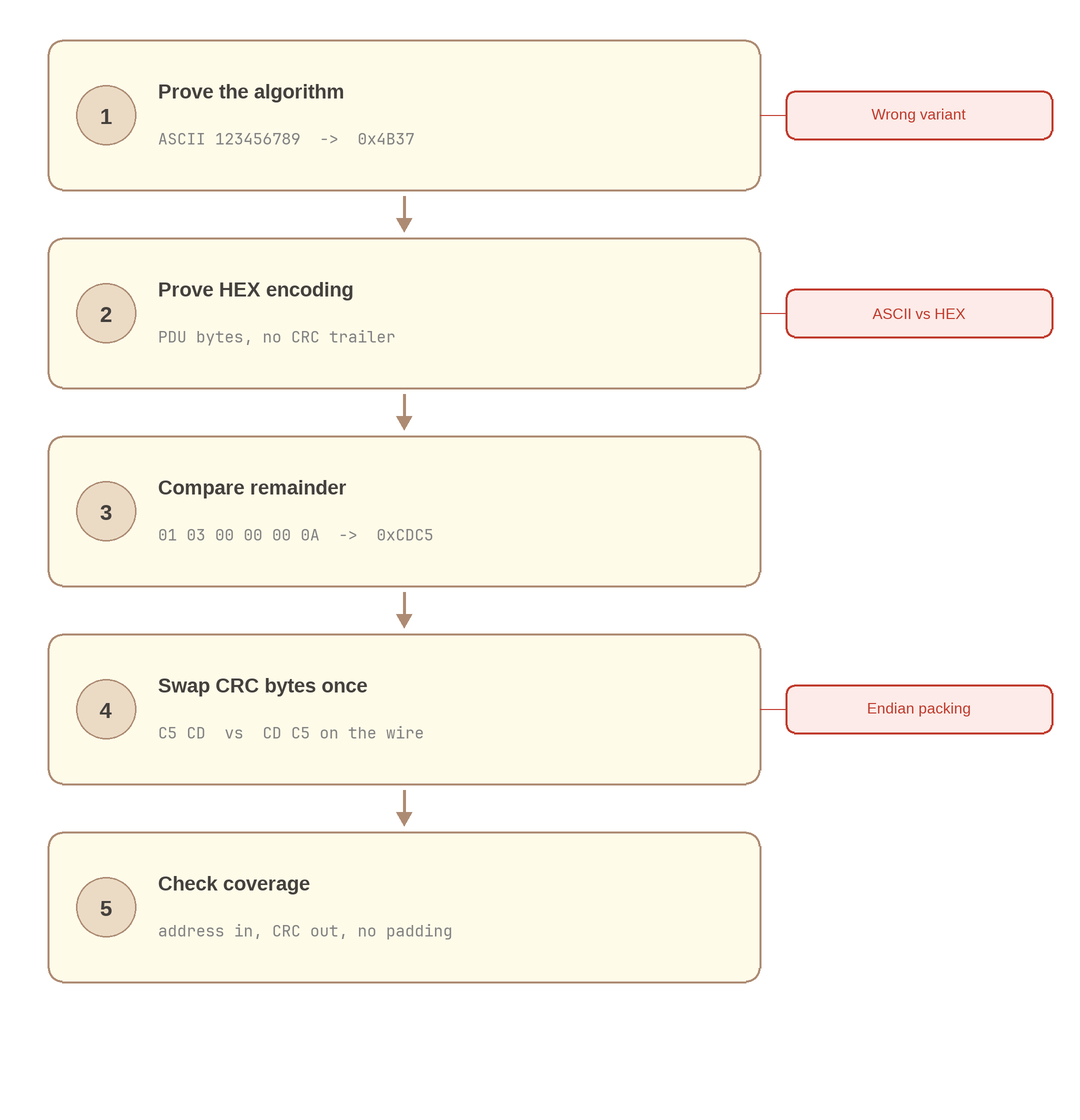
Isolate algorithm, encoding, remainder, on-wire byte order, then coverage. Most field failures die in steps 1 or 4.
A second frame for a sanity check, used in the earlier CRC guide: 01 03 00 00 00 02 should yield remainder 0x0BC4, on the wire C4 0B. If one frame matches and the other does not, you are usually including a length-dependent pad or hashing past pdu_len.
Lookup-table implementations deserve one extra look. A 256-entry table generated for CRC-16/ARC (init does not change the table, but people generate tables with the wrong poly or the unreflected 0x8005 left-shift method) will fail the check value even if the wrapper still says 0xFFFF. The CRC Lookup Table generator is there specifically so the 256 constants you paste into C match the same catalogue row as the slow bit loop.
Confirming a Frame in the CRC Calculator
Open the CRC Calculator. You want three things on screen before you trust a field dump.
Select CRC-16/MODBUS from the algorithm list — do not stop at the first "CRC-16" row. Set input to HEX and paste 01 03 00 00 00 0A (spaces are fine if the tool treats them as separators). Read the remainder as hex. Then set byte order to little-endian so the copy-paste value is C5 CD, the order that actually goes on the RS-485 pair.
The same input with CRC-16/ARC or CRC-16/IBM-3740 will produce a different remainder. That comparison is the point of a multi-algorithm calculator: you are not looking for a pretty UI, you are looking for the named row whose check value you already verified. Because the computation runs in WebAssembly in the browser, prototype firmware dumps do not have to leave the machine — the same local-processing argument as in why WASM matters for browser calculators.
If you are implementing rather than only checking, run the check vector in your unit tests:
Those two asserts catch wrong poly, wrong init, wrong reflection, and (if you also pack the frame in the test) wrong endianness. They are cheaper than another hour on the bus analyzer.
What This Does Not Fix
A correct CRC does not mean the slave will do what you wanted. Illegal function, illegal address, and exception codes are application-layer failures with a valid CRC. Conversely, CRC is still only accidental-error detection: it will not stop someone who can rewrite both payload and remainder. Use it to get frames on and off the wire. Do not use it as a substitute for authentication.
The reliable habit is boring. Name the catalogue row. Check 0x4B37. Pack low byte first. Hash the PDU you think you hashed. After that, Modbus CRC almost never "keeps failing" — it was a different CRC, or the same CRC in the other byte order.
References
- Greg Cook, Catalogue of parametrised CRC algorithms — Parameter sets and check values, including CRC-16/MODBUS (
check=0x4B37) - Ross Williams, A Painless Guide to CRC Error Detection Algorithms — Width, poly, init, refin, refout, xorout explained as an implementation contract
- Modbus Organization, Modbus Application Protocol Specification V1.1b3 — RTU frame layout and CRC-16 appendix
- Modbus Tools, Modbus Protocol Description — RTU framing and CRC placement used in field tools