Gimbal Lock is a singularity phenomenon that occurs when representing 3D rotations using Euler angles. When two rotation axes align at a specific angle (typically Pitch ±90°), one degree of freedom is lost — and any controller attempting to compensate may command joints to rotate hundreds of degrees, with catastrophic results.
"The logic is perfect. Why is the arm spinning like that?"
During my graduate research on a 6-axis robotic arm, I asked myself that question hundreds of times. The Inverse Kinematics algorithm had been mathematically verified and ran perfectly in simulation. But whenever the arm approached a certain pose, the joints would suddenly thrash — rotating hundreds of degrees at a time. The control software showed no errors. The problem lay somewhere entirely different: a mathematical flaw inherent to the Euler Angles representation itself, known as Gimbal Lock.
In this post, I'll dig into why gimbal lock occurs mathematically, and summarize avoidance strategies proven in aerospace, robotics, and game development. If you'd like to compute and visualize 3D rotation transformations yourself, the 3D Rotation Transformation Tool is a great companion.
What Is Gimbal Lock: Physical Intuition
A gimbal was originally a ring structure used to stabilize compasses on ships and gyroscopes in aircraft. Three rings rotating around the X, Y, and Z axes respectively can maintain the orientation of an inner device from any direction.
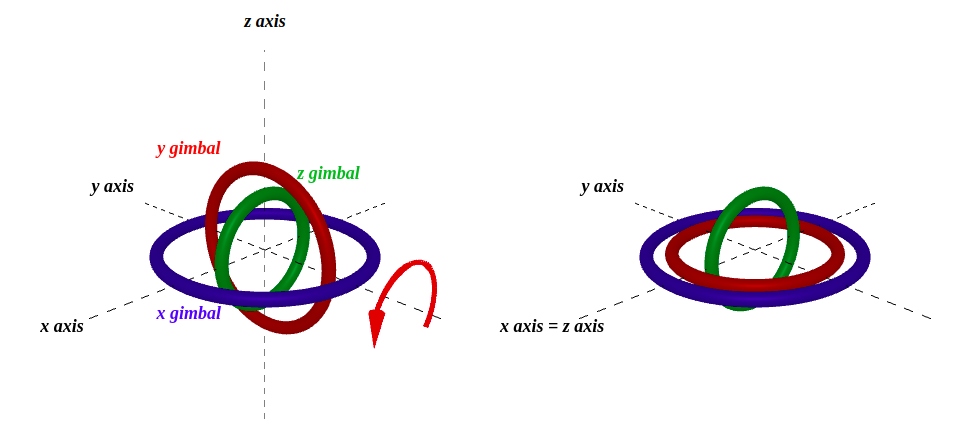
The physical gimbal structure: when the Y-axis ring rotates 90°, the X and Z axes become parallel, losing one degree of freedom
The problem occurs the moment the middle ring (typically the Y-axis or Pitch axis) reaches ±90°. At that point, the outermost ring's rotation axis and the innermost ring's rotation axis become parallel. Physically, both rings can only rotate in essentially the same direction — and despite having three rings, the number of independently representable rotation directions drops to two.
This is Gimbal Lock. The number of rings hasn't changed; two of them have simply started doing the same thing.
Why Euler Angles Have Singularities
To understand why Gimbal Lock is not merely an implementation bug, we need to look at the topological nature of the 3D rotation space.
3D rotation is mathematically defined as an operation on the Lie Group called SO(3) (Special Orthogonal Group) — the set of 3×3 orthogonal matrices with determinant 1, encompassing all 3D rotations that preserve length and orientation. Euler angles are an attempt to map this space to three real-number coordinates.
And here lies a topological barrier. The topological structure of SO(3) is such that no globally smooth coordinate system (a mapping free of coordinate singularities) exists. This is analogous to the impossibility of perfectly representing a sphere (S²) as a flat map. As a consequence of the Hairy Ball Theorem, no globally continuous unit vector field exists on SO(3). Since Euler angles are merely a coordinate parameterization, they cannot escape this barrier — at least one singularity must arise. Gimbal Lock is the most prominent example of such a coordinate singularity.
In short, Gimbal Lock is not a bug born from a poor Euler angles implementation. It is a mathematical inevitability of attempting to globally map SO(3) using only three real-number coordinates.
Mathematical Cause: Singularity of the Jacobian Matrix
To understand Gimbal Lock mathematically, we need to examine the differential relationship between Euler angles. Using the ZYX convention (Yaw-Pitch-Roll in aviation), the relationship between angular rate
where the Jacobian matrix
Computing the determinant of this matrix:
Here is the crux of the matter. When
At
The first and third columns lose their linear independence. Changes in
This is the essence of Gimbal Lock: a singularity inherent to the Euler angle coordinate system itself — a point where the coordinate system fails to map the 3D rotation space SO(3) without defect.
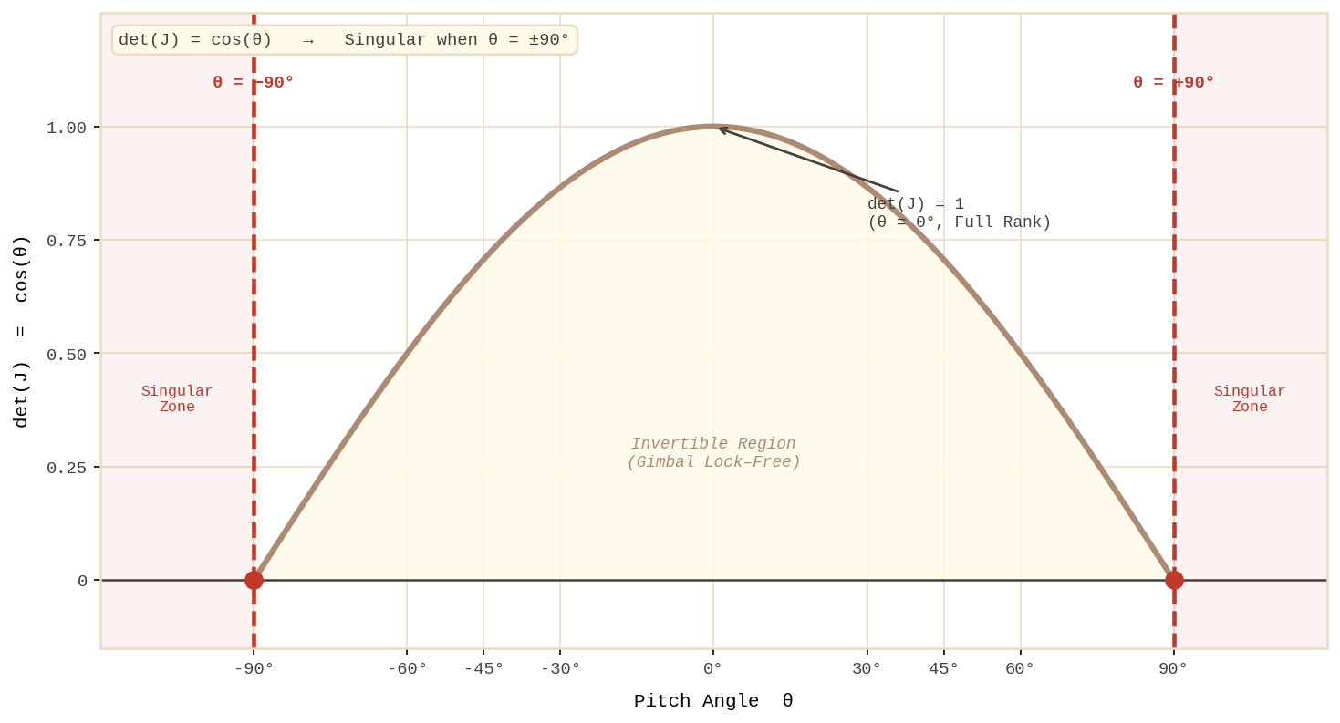
Jacobian determinant det(J) = cos(θ): it reaches zero at Pitch = ±90°, making the inverse transformation impossible
Practical Consequences of Gimbal Lock: What Actually Happens
The theory may feel abstract, so let's look at what actually happens at the code level.
A commonly used formula for converting a quaternion to ZYX Euler angles:
As pitch approaches ±90°, both arguments passed to arctan2 approach zero. At that point, atan2(0, 0) is mathematically undefined, and accumulated floating-point errors cause Roll and Yaw values to blow up erratically.
Returning to my robotic arm project: the fully vertically extended pose was exactly the Pitch ≈ 90° condition. The end effector's orientation error reached tens of degrees, and the controller responded by issuing commands to rotate joints hundreds of degrees in an attempt to compensate.
Avoidance Strategy 1: Switching to Quaternions
The most fundamental solution is simply not to use Euler angles as the internal representation. Unit quaternions can represent the 3D rotation space SO(3) without singularities.
Mathematically, quaternions are defined on SU(2), which is the double cover of SO(3). That is, each rotation is represented by two quaternions,
After switching to quaternions in the robotic arm project, the code became:
The joints began moving stably through all configurations, including the fully vertical extended pose.
The quaternion SLERP (Spherical Linear Interpolation) formula is:
where
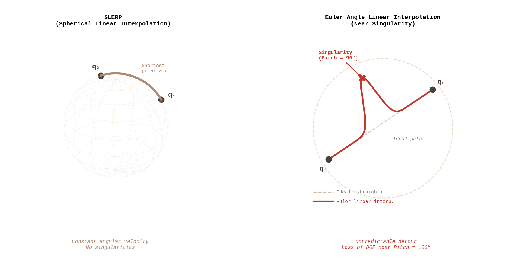
SLERP (left) follows the shortest arc on the unit sphere. Euler interpolation (right) takes an abnormal detour near the singularity
Avoidance Strategy 2: Singularity Detection and Path Replanning
In real-time control systems, switching the pose representation alone is sometimes insufficient. Input may arrive as Euler angles, or the system may need to interface with legacy components. In such cases, proactively detecting proximity to a singularity and replanning the path is an effective strategy.
A common approach in aviation attitude control systems is to monitor the condition number of the Jacobian:
NASA's Space Shuttle control system used a similar "Representation Switching" strategy. Henderson's (1977) NASA technical report systematically covers the relationships between Euler angles, quaternions, and transformation matrices as applied to Space Shuttle attitude analysis. When the attitude approached a certain threshold, the system automatically switched from Euler-based control to quaternion-based control. (NASA Technical Report: Euler Angles, Quaternions, and Transformation Matrices for Space Shuttle Analysis)
Avoidance Strategy 3: Hybrid Use with Rotation Matrices
3×3 Rotation Matrices are also singularity-free. By directly representing SO(3) using nine values, they are immune to Gimbal Lock. They are a particularly natural choice in rendering pipelines or computation-heavy linear algebra environments.
Transforming a vector with a rotation matrix requires just 9 multiplications and 6 additions:
However, repeated matrix multiplication gradually breaks down orthogonality due to floating-point error accumulation. To prevent this, Gram-Schmidt orthonormalization must be applied periodically. This is why quaternions are preferred over matrices in practice — normalization for a quaternion costs just one square root:
Experiencing Gimbal Lock with a Tool
The fastest way to see all of this in action is to plug in numbers yourself. The 3D Rotation Transformation Tool supports real-time conversion between quaternions, Euler angles, and rotation matrices, with results visualized immediately in an interactive 3D viewer.
To experience Gimbal Lock directly:
- Set the input type to Euler Angles and the rotation order to ZYX.
- Set the Y value (Pitch) to 90°.
- Vary the X value (Roll) from 0° to 45° to 90°.
- Then vary the Z value (Yaw) across the same range.
You'll see that changes in X and Z produce identical rotations in the 3D view. Two parameters generating the same rotation — that is the reality of Gimbal Lock.
Conversely, switch the input type to Quaternion and repeat the same operations. You'll find that any input produces independent rotations in every direction.
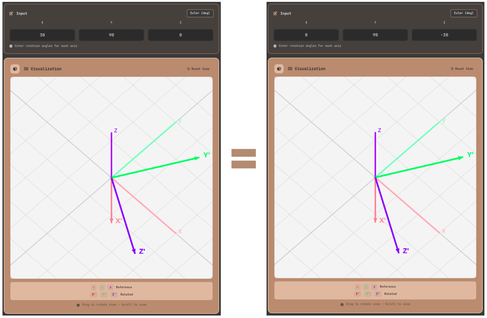
Gimbal Lock in the 3D Rotation Transformation Tool: with ZYX Euler at Pitch=90°, changing Roll and Yaw independently produces identical rotations
Field-Specific Avoidance Strategies
Aerospace: Dual Representation Strategy
NASA's Space Shuttle attitude analysis system uses quaternions internally while displaying Euler angles only on the pilot interface. During the display conversion, the system always checks for proximity to singularities and remains ready to switch to an alternative representation.
Commercial aircraft are trained to treat a pitch angle exceeding roughly ±70° as an Unusual Attitude, triggering special recovery procedures. This is also a safety margin designed so that human pilots can intervene before Gimbal Lock becomes an issue.
Robotics: Singularity-Avoiding Path Planning
The MoveIt! framework for ROS (Robot Operating System) includes built-in path planning algorithms that avoid joint-space singularities. When it detects a joint configuration close to a singularity, it automatically inserts intermediate waypoints to route around it.
Industrial robot manufacturers KUKA and ABB define singularity proximity in their respective controllers using criteria such as:
- Minimum Singular Value of the Jacobian < threshold
- Condition Number > a specified multiple
When these conditions are met, the controller slows down or replans the path to prevent abrupt joint motion.
Game Development: Layered Rotation Design
In game engines, character head rotations rarely exceed 180°, so Gimbal Lock seldom causes real problems in practice. However, for camera systems and physics-based animation (Ragdoll), quaternion SLERP is essential.
A practical pattern in Unity:
Conclusion: Choosing the Right Representation Is Engineering
Gimbal Lock is a mathematical singularity. It is a topological inevitability of attempting to globally coordinate SO(3) with Euler angles, and no implementation optimization can resolve it at its root. There is only one way to avoid it: move to a representation space that has no such singularity.
Unit quaternions, as the double cover of SO(3), represent every pose without singularities. The notation
Use Euler angles only for human-readable interfaces. For all internal computation and interpolation, always use quaternions or rotation matrices. This is the design principle validated over decades in aerospace, robotics, and game development alike.
One final note: it's genuinely difficult to internalize these concepts without direct experimentation. Head to the 3D Rotation Transformation Tool, push the Pitch in Euler angles to 90°, then represent the same pose as a quaternion. The moment you see the difference with your own eyes, Gimbal Lock will no longer be an abstract theory.
References
- Diebel, J. "Representing Attitude: Euler Angles, Unit Quaternions, and Rotation Vectors", Stanford University, 2006 — The most systematic reference for the mathematical relationships between Euler angles, quaternions, and rotation vectors. The ZYX Jacobian singularity derivation in §5.6 directly corresponds to the mathematical explanation in this post.
- Shoemake, K. "Animating Rotation with Quaternion Curves", SIGGRAPH 1985 — The paper that first introduced the SLERP concept to computer graphics.
- Henderson, D. M. "Euler Angles, Quaternions, and Transformation Matrices for Space Shuttle Analysis", NASA-CR-151435, 1977 — NASA technical report systematically covering the relationships between Euler angles, quaternions, and transformation matrices as applied to Space Shuttle attitude analysis.
- Siciliano, B. et al. Robotics: Modelling, Planning and Control, Springer 2009 — The textbook reference for singularity theory in robotics.
- MoveIt! Documentation "MoveIt Concepts" — Official documentation for the ROS-based singularity-avoiding path planning framework.