Let's explore CRC (Cyclic Redundancy Check), an essential component in digital communication and data storage.
CRC is an error detection algorithm that plays a crucial role in various protocols and systems. While it may seem simple, there's much to understand for practical implementation. This article covers content for those encountering CRC for the first time or looking to apply it in real-world scenarios. If you need to calculate CRC values, you can use the CRC Tool.
Why Do We Need CRC?
What's most important when transmitting or storing data? Verifying that the data has been delivered accurately. Countless factors can corrupt data: noise in network cables, physical damage to storage media, electromagnetic interference, and more.
CRC is an error detection algorithm designed to solve these problems. Unlike simple checksums, it's based on mathematically rigorous Polynomial Division, enabling it to detect complex errors with high probability, such as reordered bytes or specific patterns of bit flips.

Basic CRC workflow illustrating how a checksum is generated from input data, appended during transmission, and verified on the receiver side.
How Is CRC Used in Practice?
1. Foundation of Network Communication (Ethernet)
CRC is used in Ethernet (IEEE 802.3), the foundation of internet communication. Every Ethernet frame contains a 32-bit FCS (Frame Check Sequence) field that includes a CRC-32/ISO-HDLC checksum. Network switches and routers automatically verify this value, discarding corrupted frames and requesting retransmission.
2. Industrial Automation Sites (MODBUS)
The MODBUS RTU protocol, a standard in factory automation systems, uses CRC-16/MODBUS for data integrity. Industrial environments have severe electromagnetic noise, making CRC essential for reliable data transmission between PLCs (Programmable Logic Controllers) and sensors.
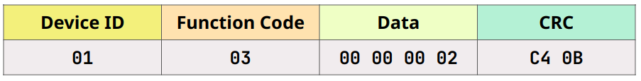
MODBUS RTU request frame structure showing Device ID, Function Code, Data field, and CRC-16/MODBUS checksum (01 03 00 00 00 02 C4 0B).
3. Automotive Electronic Systems (CAN Bus)
The CAN (Controller Area Network, ISO 11898) bus, used for communication between ECUs (Electronic Control Units) in modern vehicles, employs CRC-15/CAN. Since safety-critical data like steering and braking is transmitted, functional safety standards such as ISO 26262 emphasize these error detection mechanisms.
4. Embedded Sensor Communication (1-Wire)
Low-power embedded devices like temperature sensors often use Maxim's 1-Wire protocol, which implements CRC-8/MAXIM-DOW. An 8-byte data reading from the sensor is followed by a 1-byte CRC, detecting data corruption that can occur over long cables.

Embedded sensor data packet with the final CRC byte highlighted, demonstrating CRC-based error detection in low-power communication protocols.
CRC Algorithm Configuration Parameters
Even with the same bit width (e.g., 16 bits), MODBUS, USB, and XMODEM produce different results because their parameters differ. According to Ross Williams's CRC Guide, CRC algorithms are defined by:
- Generator Polynomial: The divisor used in division. Example: CRC-16/ANSI uses
0x8005. - Initial Value: The value loaded into the register at calculation start. Usually
0x0000or0xFFFF. - XOR Output: XOR value applied to the final calculation result.
- Input/Output Reflection: Whether to reverse bit order within bytes during processing.
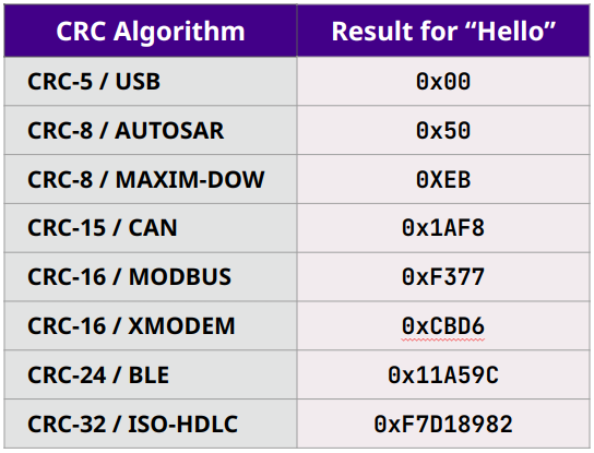
Comparison of CRC results for the same input string ("Hello") across multiple CRC algorithms, highlighting how different polynomials and parameters produce different checksums.
Practical Implementation: MODBUS CRC Example
Let's calculate the CRC for a MODBUS RTU protocol request frame 01 03 00 00 00 0A that reads 10 registers.
Step 1: Data Preparation
First, prepare the data excluding the CRC in hexadecimal:
- Input Method: Select CRC-16/MODBUS
When entering this value in the CRC Tool, select 'HEX' as the input method and enter with spaces separating the values.
Step 2: Algorithm Configuration and Input
- CRC Algorithm: CRC-16/MODBUS
- Output Format: HEX
- Hex Style: 0x48
- Byte Order: Little Endian (MODBUS uses Little Endian)
- Byte Format: Byte Separated
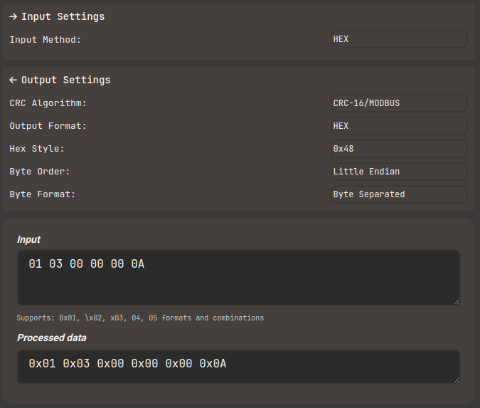
CRC calculator interface with hexadecimal input mode selected and a MODBUS request frame entered in Computools
Step 3: Result Verification
CRC-16/MODBUS calculation result: 0xC5 0xCD
Since MODBUS uses little endian, it's appended to the data in 0xC5 0xCD order during actual transmission.

CRC calculator output showing calculated checksum with little-endian byte order representations in Computools
Step 4: C Code Implementation
Performance Optimization: Lookup Table
Bit-wise calculation is slow due to the high number of loops. In practice, performance is improved by approximately 10x or more by using a lookup table with 256 pre-calculated values, processing byte by byte.
CRC's Error Detection Capability and Limitations
Detectable Errors
CRC detects the following accidental errors with very high probability:
- Single-bit and adjacent 2-bit errors: 100% detection.
- Odd number of bit errors: 100% detection when the generator polynomial includes the
- Burst Errors: 100% detection of consecutive errors within the CRC bit width (n).
Security Limitations
CRC is a tool for preventing accidental data corruption and, unlike cryptographic hashes (SHA-256, etc.), cannot be used for security purposes. Malicious attackers can reverse-calculate to modify data while maintaining the same CRC value.
References and Further Reading
- Ross Williams, "A Painless Guide to CRC Error Detection Algorithms" - The most recommended document for understanding CRC operation principles and parameters.
- Modbus Tools, "Modbus Protocol Description" - The standard for MODBUS CRC implementation.
- Analog Devices, "Understanding and Using Cyclic Redundancy Checks with Maxim 1-Wire and iButton Products" - Covers CRC application in embedded 1-Wire systems.
- IEEE 802.3 Standard, "IEEE Standard for Ethernet" - Defines CRC-32 specifications for Ethernet frames.
Data integrity is directly tied to system reliability. When implementing, it's important to verify with tools like the CRC Tool and accurately follow standard specifications.